Steel Wardrobe Door System – Concord 24mm
Concord is one of our best value made to measure sliding wardrobe doors systems. The visible vertical frame is 24mm wide and acts as your handle. Made from high-quality steel, about 20% thicker than most equivalent steel products found in DIY stores, and also has superior track and running gear by comparison.
Please note: Letterbox 3 panel doors have a middle panel of 350mm, unless you specify otherwise.
View our ‘Further Information‘ page to see how to measure and install, for technical specifications and other useful information.
In our Good/Better/Best ranking, this is part of our GOOD range.
Prices start at £127 for made to measure mirror door up to 2.48m tall and 1.0m wide. Other finishes will be more expensive. Doors over 1.0m wide will cost an extra 30%.
Click on the gold tab to the right to ‘Pick a different range’. The next step up in cost is Laval or Halifax, which have a heavier frame around the door.
All glass doors use family safe glass to BS EN 12600, and running gear has a 10 Year Guarantee.
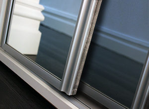
Silver framed Mirror Doors with Brush Dust Strip
Opening size
Door design


Door panel colours
Wood panels
Plain panels
Mirror panels
Standard colour glass
Special colour glass
- Technical Specifications
- How to Measure
- How to Install
1. Bottom Roller for Steel System
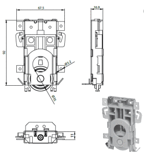
Body made from galvanized structural steel, designed for snap and screw fixing. The moving part is adjustable within the 0-32 mm range by means of an adjusting bolt and is provided with an anti-jump feature. The roller has a wheel of a high-strength plastic with an embedded sealed ball bearing. Resistance: up to 60 kg/2 rollers, up to 50,000 open/close cycles.
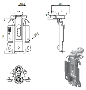 2. Twin Wheel Top Guide
Body made from galvanized structural steel, designed for snap and screw fixing. The guide features wheels of high-strength plastic and vibration damping rubber. The moving part allows the wheels to be adjusted within the 0, 16, 32 mm range. The wheels, fixed to an elastic moving arm, precisely follow the track.
 3. Steel Double Bottom Track.
Track made from galvanized zinc-coated steel sheet, fi-nished with polyester paint or simulated wood film. Material thickness: 0.5 mm. Track length: 5000 mm.
 4. Steel Double Top Track.
Track made from galvanized zinc-coated steel sheet, fi-nished with polyester paint or simulated wood film.
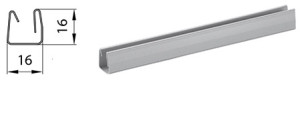 5. Steel Rail.
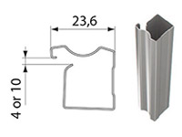
A rail for 4 or 10 mm mirror panels to steel door systems. Made from galvanized zinc-coated steel sheet, finished with polyester paint or simulated wood film. Material thickness: 0.5 mm.
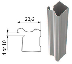 8. Concord Steel Stile, 2.75 m.
A stile for 4 or 10 mm mirror panels to steel door systems. Made from galvanized zinc-coated steel sheet, finished with polyester paint or simulated wood film.
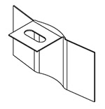 10. Top Positioner
A component that holds in position steel system doors (note: not included as standard but can be purchased)
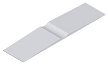 11. Positioner, grey plastic.
Sets the S100 system door leaf in the end position. It is stuck to the top track (note: not included as standard but can be purchased)
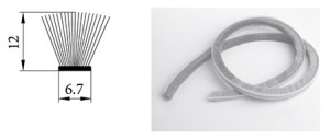 12. Self-adhesive Dust-stop
Brush 6.7 x 12.
A brush designed to seal the space between door leaves and to stop dust. Hair length: 12 mm
(note: not included as standard but can be purchased).
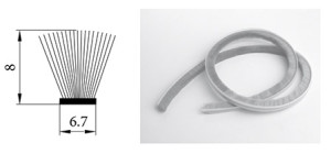 Self-adhesive Dust-stop Brush 6.7 x 8.
A brush designed to seal the space between door leaves and to stop dust. Hair length: 8 mm (note: not included as standard but can be purchased)
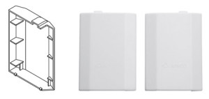 13. Bottom Roller Guard left/right
A set of bottom roller guards (right and left) for steel systems (note: not included as standard but can be purchased).
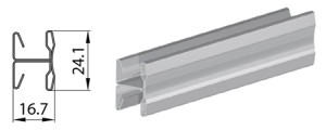 14. Steel Connector Rail, 2.75 m.
A universal profile designed for horizontal and vertical joints between different panel types with a thickness of 4 and 10 mm. Made from galvanized zinc-coated steel sheet, finished with polyester paint or simulated wood film.
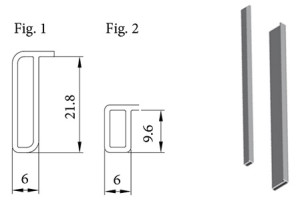 15. and 16. Spacer for steel system with combination panels.
A universal profile designed for horizontal and vertical joints between different panel types with a thickness of 4 and 10 mm. Made from galvanized zinc-coated steel sheet, finished with polyester paint or simulated wood film.
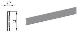 17. Stick-on Decorative Strip.
Length: 2.4 m.
A decorative steel strip to be stuck on the steel system panel. Made from galvanized zinc-coated steel sheet, finished with polyester paint or simulated wood film.
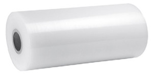 18. Self-adhesive Safety Backing.
Self-adhesive Safety Backing, 100 mm x 250 m. Transparent film. Packaging: 100 m2/roll, 10 cm wide. Weight: ~2.50 kg/roll. Availability: continuous.
Self-adhesive Safety Backing, 200 mm x 250 m. Black film. Packaging: 50 m2/roll, 20 cm wide. Weight: ~5.00 kg/roll. Availability: continuous.
Self-adhesive Safety Backing, 300 mm x 250 m. Transparent film. Packaging: 75 m2/roll, 30 cm wide. Weight: ~7.50 kg/roll. Availability: continuous.
Self-adhesive Safety Backing, 400 mm x 250 m. Transparent film. Packaging: 100 m2/roll, 40 cm wide. Weight: ~10.50 kg/roll. Availability: continuous.
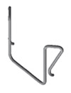 19. Buffer Strip Clip.
A clip preventing the buffer strip from coming unstuck. (note: not included as standard but can be purchased).
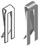 20. Buffer Strip Clip.
A clip preventing the buffer strip from coming unstuck (note: not included as standard but can be purchased).
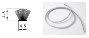 21. Self-adhesive Buffer Strip, 4.8×5 or 4.8 x 4.
A strip designed to dampen door impact against the wall and eliminate minor wall irregularities (note: not included as standard but can be purchased).
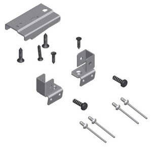 22. Steel System Soft Closer Accessories.
These items are used to fix the
universal soft closer to
a steel system door leaf.
The steel system door closer
accessories include:
– Trigger
– Soft closer adapter, right
– Soft closer adapter, left
– Adjusting screw 2.9 x 19mm (1 pce)
– Trigger mounting screws 3.5 x 16mm (2 pcs)
– Soft closer adapter mounting screws 2.9 x 13mm (2 pcs) – Soft closer mounting screws M3 x 16 mm (4 pcs)
– Soft closer adapter mounting rivets (4 pcs) Application: S100.
(note: not included as standard but can be purchased)
 23. Universal Soft Closer.
It ensures that the door leaf closes softly to its end position. The soft closer features an air damper, which gu-arantees durability and performance stability throughout its useful life.
The design of the soft closer body allows it to be used as a left-hand or right-hand closer. The installation of the soft closer on the steel system-based door leaf is possible with the use of the steel system door closer accessories 099245. The soft closer is available in two versions:
099233 – soft closer for doors of up to 25kg in weight.
099234 – soft closer for doors of 25 to 50kg in weight. Application: S100, A100, A200.
Availability: continuous.
(note: not included as standard but can be purchased)
Important: Please remember, we always need the MINIMUM height dimension of A, B or C. Measure carefully, so we don’t make your doors too big. Use the Maximum of width D or E (this is less critical than the height). If in doubt call or email us with your questions.
Option 1: Fitting Floor to Ceiling and Wall to Wall:

This is the easiest to measure and install. If you have skirting’s, you will need to remove a portion where the doors touch the wall, or install wall liners as in ‘Option 2’.
Option 2: Using Floor and Wall Liners
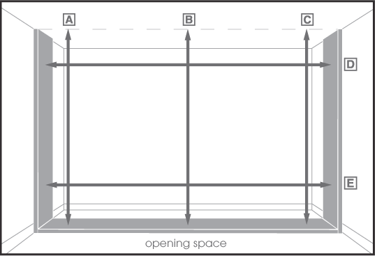
We recommend this if you walls are not vertical, and floor is not flat (or if you are installing on top of carpet). We can supply wall and floor liners in 18mm MFC in 3 core colours (white silver or oak). Pack out the liners to create vertical and horizontal surfaces. Calculate your DOOR & TRACK width and height measurements from inside the liners.
Option 3: Wall to End Panels
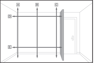
We have 18mm MFC end panels in 3 core colours (white, silver, oak), or alternatively, use MDF and decorate to exactly match your wall colour. End panels can be used in conjunction with ‘Wall and Floor Liners’ as shown in Option 2.
Option 4: Using Infill’s
For Openings Wider than 5000mm (Made to Measure Doors).
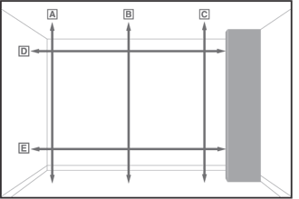
Only do this if your opening is wider than our widest track length of 5000mm. Infill’s can be placed on the left and right to centre your wardrobe. Again, we recommend MDF and decorate to match you walls, or use our range of end panels. Infill’s can be used in conjunction with ‘Wall and Floor Liners’ as shown in Option 2.
Option 5: Reducing Ceiling Height
For ceilings higher than 2500mm (Made to Measure Doors).
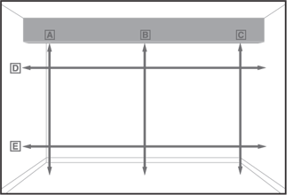
Again we recommend a timber and/or MDF construction, decorated to match your walls, or use our range of MFC end panels or floor liners. Ceiling reduction can also be used in conjunction with ‘Wall and Floor Liners’ as shown in option 2.
Option 6: Angled Ceiling (Please contact us for angled doors)
For angled ceilings:
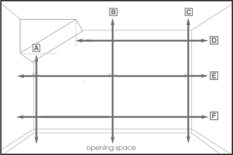
Due to the nature of angled wardrobe doors, we need you to take additional measurements in order for us to manufacture your doors to fit the opening.
Here, measurement A is the height from the floor to the base of the angled section (referred to within the design tool as ‘Short Height’) and measurement D is the width of the opening at the ceiling (between the tall wall, and where the angled section meets the ceiling – this is referred to in the design tool as ‘Ceiling Width’). The smallest of measurements B and C, and the largest of measurements E and F are the ‘height’ and ‘width’ of your opening respectively.
1. Cut the tracks
Carefully measure the width of the opening at top and bottom, and reduce the lengths measured by about 2-3 mm. Measure off the required track length, marking the future cut line on the tracks. Use a fine-toothed metal cutting saw to cut off the redundant part of the tracks.
Advice:The tracks to be installed should be about 50 mm longer than the opening width. This spare length will make it possible to avoid measurement errors and it is easy to trim. Take care not to damage the track surface while cutting. In order to facilitate top track cutting, insert 38 mm thick wood blocks or a reversed piece of track into the track. This will prevent track deflection during the cutting process.
2. Install the top track
Fix the top track with screws, offsetting its flat surface by 5 mm from the door face (inwards). Install the top track with the shade line facing forward in order to mask ceiling irregularities. If a multiple-track system is installed, fix the other tracks so that they fit tightly against each other along the entire length.
Advice: Before you start installation use a detector to make sure there is no electrical wiring at the screw fixing points. Avoid applying excessive force when tightening screws to prevent track deformation. Use flat-head screws for best results. The surface to which the track is fixed must not be curved.
3. Install the door
Lay the bottom track on the floor, offsetting it about 27 mm from the door face (inwards). Use a Philips screwdriver and the adjusting bolt to move bottom rollers out about 10 mm. Fully insert the door leaf in the top track, taking care not to damage the bottom rollers, then align the bottom end of the door leaf with the bottom track and slowly lower the leaf, letting the rollers snap into the track guides.
Advice: Before you install the doors, put a cardboard sheet on the bottom track to prevent damage to track surface. When the doors are already in position, remove the protective cardboard.
4. Install the bottom track
Use a level to make sure the door is exactly plumb; move the bottom track as necessary. Check if the door travels smoothly along the entire width of the opening. Having precisely set the bottom track, fasten it to the floor. Having installed the track, put the other door leaves in their respective tracks.
Advice: Before you fix the bottom track, make sure that it is positioned exactly parallel to the top track. With soft floor covering, before you fix the bottom track, cut out a strip of about 55 mm in width and replace it with a 55 mm timber batten. Alternatively, put a 100 mm floor batten between the floor covering and the bottom track. Avoid applying excessive force when tightening screws to prevent track deformation. Use flat -head screws for best results.
5. Adjust door position
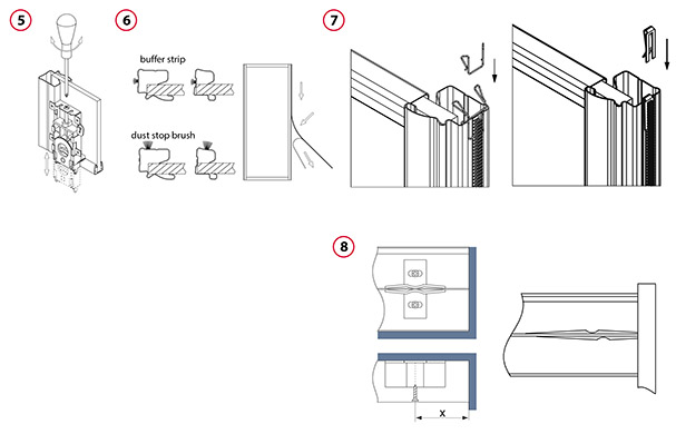
Adjust door position by means of a Philips screwdriver and the adjusting bolts in the bottom rollers so that the doors fit tightly against the wall along the entire length. Door-to-floor clearance is adjustable between 10 and 40 mm (2 to 32 mm from the bottom track).
6. Fix the buffer and dust-stop brush strips
Having installed the doors, remove protective backing from the door profiles. With the backing removed, you can fix the buffer strips and the dust-stop brush strips. To ensure good adhesion of the brush strips to the profiles, gently clean the profiles with alcohol or white spirit. Fix the strips, working from top to bottom. Cut off excess strip.
7. Fix the buffer strip clip
To fix the clip 099249 or 099249A, the door must first be installed and adjusted. After that operation, fix the buffer strip and then mount the clip. For easier and correct installation, we recommend that the door should be taken off the tracks.
Advice: For details of the buffer strip clip installation see separate instructions, “Technical information– fixing the buffer strip clip” available on our website in the section designated for Authorised Partners.
8. Fix the buffer strip clip
Fix the positioner 099265 to the top track so that it fits against the middle part of the track at an appropriate distance from the wall. Cut the positioner 099259PLS to the right size and fix in the middle of the top track so that the door abuts on the side wall of the unit when closed.
For the Montreal profile
x = 32 mm, where no buffer strip is used,
x = 37 mm, where a buffer strip is used.
For the Halifax profile
x = 32 mm, where no buffer strip is used,
x = 37 mm, where a buffer strip is used.
1. Installation of the universal soft closer in aluminium systems
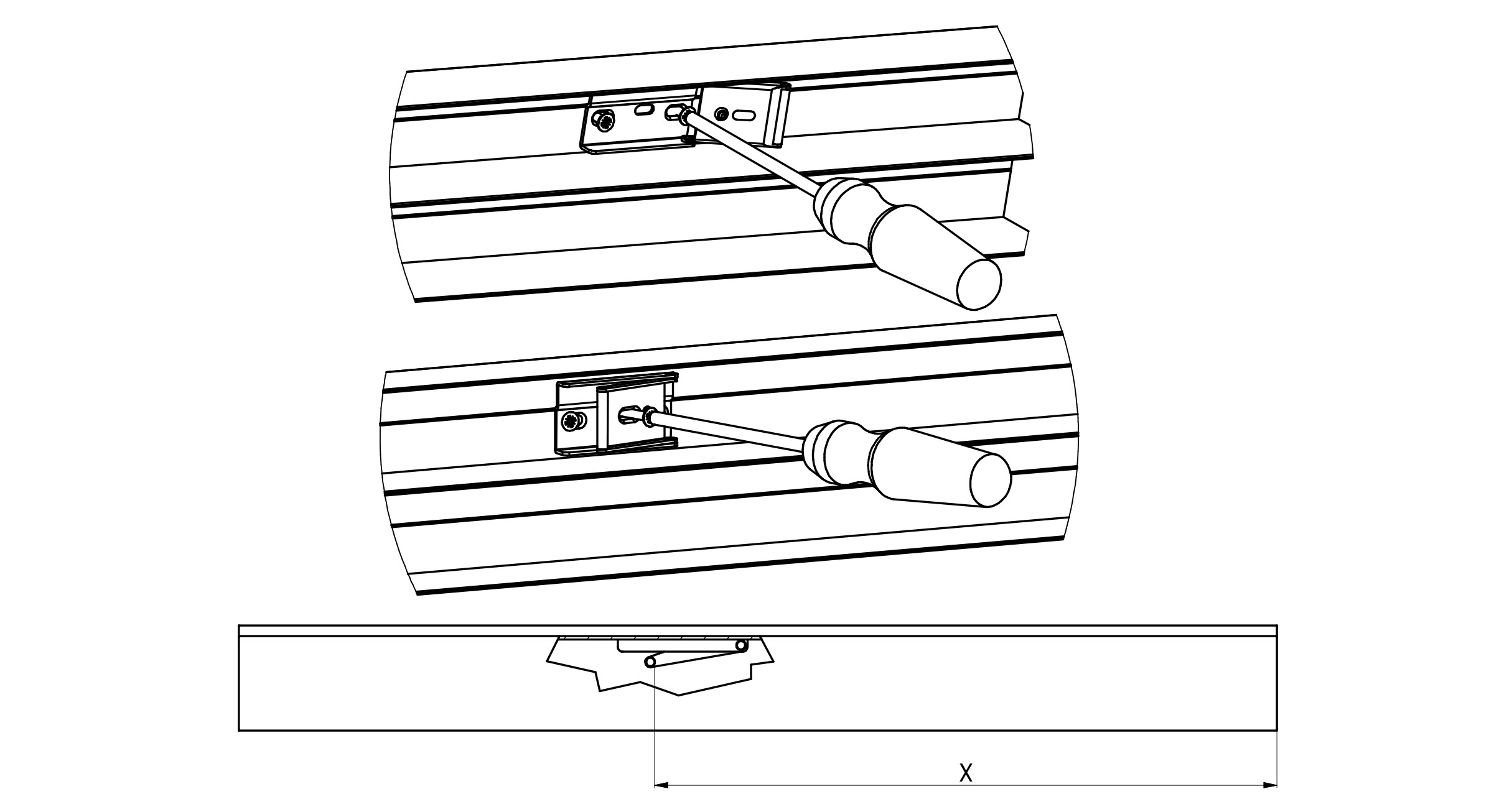
Fasten the universal soft closer 09923X to the narrow rail by means of adapters and 3.5 x 23 screws (aluminium system soft closer accessories). Having fastened the closer, release the activator on the door, so it sits inthe position shown, then measure the distance “X” from the closing edge of the door.
 2. Installation of the soft closer trigger
Screw the activator plate into the track so that the bar is the same distance from the wall (“X”). First screw the main plate to the track, and then a single screw through the piece that rotates down to hold it up in position. This last single screw and the grub screw allows you to adjust the height of the bar if required.
Install the door and adjust the height of the door, so the soft close unit meets the activator plate.


